A Cooking Machine – Electronics Assembly, Programming & 3D Design Printing
This post is the thirteenth in a series detailing the processes behind the research, design, material selection, online audience building, fundraising, application development, assembly, and programming of a cooking machine. See the column Stories of Food & Tech here.
In this post, I’ll share the final touches on the electronics assembly, TFT touch screen programming, and my 3D design printing processes that allow me to 1) install the stepper motor onto the cooking pot and 2) control the stirrer motion.
TFT touch screen modification of controls
While a lot of progress was made in post 12, the reality is that the initial TFT touch screen design you see in post 12 doesn’t fully serve the functions I want to implement on the cooking machine; it was missing a few modifications to the touch screen controls/displays. More specifically, in the last few weeks I replaced the liquid pump sliders with ON/OFF controls and replaced the temperature slider with temperature measurement readings. The corresponding sections below will explain these controls/displays in more detail.
Digital Switch
My original design included two external ON/OFF toggle switches shown in the Image 1 below. However, as you can see, too many wires between the two liquid pumps and the switches made it difficult to modify the circuit board. In addition, it was hard to press down on the toggle switches since they are taped to the liquid pump, and their positions were not fixated onto any external wall of the cooking pot.
Image 1. Original Liquid Pump Circuit with Toggle Switches
Moving forward, I knew I needed to eliminate these external switches to maneuver the oil and water liquid pumps more easily. As a result, I found an SPST(single pole single throw) digital IC (integrated circuit) that can be combined with the TFT touchscreen to send digital signals. The IC, shown in the Image 2 below, essentially works as a digital switch that allows me to digitally turn ON/OFF the liquid pump using pre-programmed instructions.
Image 2. Digital SPST Switch
After meddling with this type of IC for a few hours, I was able to implement two of them on my water and liquid pumps and cleaned up some of the unnecessary wirings on the circuit board. I also modified the TFT touch screen code to send ON/OFF signals directly to the water and oil pumps. Image 3.1 and 3.2 below show the new pump circuit and the TFT touch screen modification.
Image 3.1(left) New Liquid Pump Circuit with Digital Switches Image 3.2(right) Modified Display for the TFT Touch Screen
Thermistor
My initial plan was to have a temperature control slider. First, however, I needed to reverse engineer my current induction cooker, integrate my TFT touchscreen with the induction cooker electronics, and program it to control the heating temperature directly. This whole process will be another semi-large project to do. As a result, I only use a thermistor to send temperature measurement data that are read from the pot- both the thermistor and its values are shown below.
Image 4.1(left) Thermistor Circuit Image 4.2(right) Thermistor Values Displayed on Console
In addition to collecting the data, I have also been working on displaying it onto the TFT touchscreen. I have also modified the overhead safety alarm to turn red if the temperature value exceeds the temperature threshold of the onboard electronics.
Image 5. Overheat Safety Alarm(top right) Shown after Reaching Temperature Limit
3D design & printing
Moving from data collection and display, this section details one of the most exciting experiences of my project- the making of the stirrer itself. In this process, my goal was to design a motor supporter that could hold the stepper motor right above the stirrer while strapping itself onto the cooking pot without me holding it manually. This was where my creative thinking and problem-solving skills came into practice. Then, I need to draw the 3D model in SolidWorks and print out my 3D model using a 3D printer.
Starting, I was worried if I could get this section done at all since it’s been more than a year since I used 3D model design software, and I don’t have a 3D printer. “Don’t worry. Everything will work itself out.” I told myself.
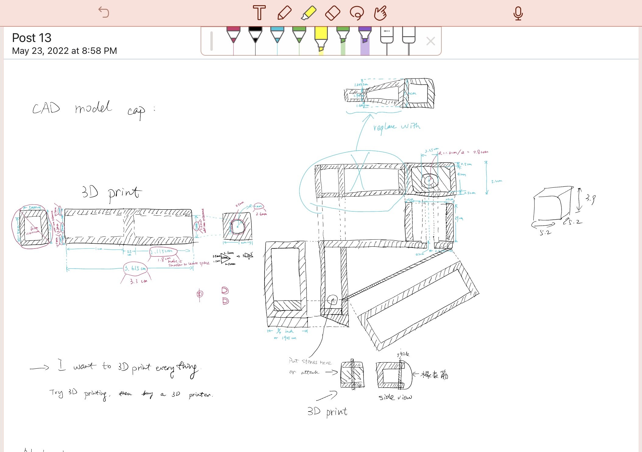
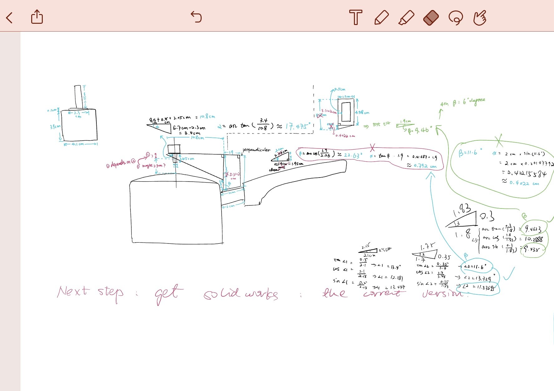
After spending some time measuring the cooking pot, the stepper motor, and the stirrer I was using, I completed some initial design drawings shown in Image 6 below. I included the designs for both the motor supporter and a connector module, which connects the stepper motor’s spinning shaft to the stirrer shaft. The initial sketches are coupled with some more final designs in SolidWorks.


Image 6. Design for the Motor Supporter and Stirrer Connector(top left)
Image 7.1 3D Model for the Motor Holder
By working through SolidWorks, I discovered that it was difficult to print the motor holder because it required the 3D printer to print certain parts in the air without solid base support. Therefore, I split it into two pieces, while also adding more support to my design.
Image 7.2 3D Models of the Motor Holder Splitting into Two (left: top half of the model, right: bottom half of the model)
Image 8 3D Model for the Stirrer Connector (left: connected to the motor shaft, right: connected to the stirrer pole)
Image 9 below shows the final successful print results!
Image 9. 3D Printing Progress of the Models Designed Above (left: top half of the model, right: bottom half of the model)
Unfortunately, the filament I used (PLA) this time can only withstand 200 degrees Celsius, which is lower than the cooking temperature. In the future, I also want to print parts that can withstand a high degree of temperature.
Video
This video shows the final result of my work for post 13. It explains how the liquid pump works and how the motor supporter works.
Final thoughts
For my next and final post, I’ll wrap up my hardware design and share the software application for this cooking machine! Stay tuned :)


